When working on various Neopixel projects, I often find myself picking up an extra light that seems interesting. One of these I’ve had lying around for a while is the m5stack Hex Unit.
The m5stack ecosystem is a pluggable set of microcontrollers, sensors, lights, et cetera, many of which connect using 4-pin Grove connectors. I quickly realised this was a different world than I’m used to, so I gathered a few Grove-specific things like cables and breakout boards, and decided it was time to try it with a Pico (2).
Initial Setup
Like many Neopixel units, the Hex Unit requires consistent 5V power. I’ve tried using a 3.7 V battery and boost converter in the past, but generally the results haven’t been great. I’ve seen dimmed colours, flickering, and the like with setups that use more than 50 lights. Even though this unit has 37 lights, I decided not to focus on the battery up front, and used the VSYS pin on the Pico, which passes the 5 V power from the board’s USB connector on to the light.
I read the spec sheet and confirmed that these are WS2182 lights, meaning they only use one data pin and not a second “clock” pin. I wired everything up using a breadboard, a Grove breakout board, a Pimoroni Pico Plus 2W, and then started planning out the code.
Beyond X and Y
I quickly realised that the biggest challenge was the layout of the unit:

With pixel curtains and grids, you can easily use x/y (or row/column) to construct arrangements of lights. The Hex Unit has a half-unit offset in each row, and each row has a different number of lights than its neighbours. Unless you’re only planning to make everything a single colour, you need a way to represent which pixels are physically next to each other in all three axes.
After some thought, I came up with a few “layouts”, or ways of referring to each pixel. The first way was simply to represent the unit as a series of rings:

Each ring starts at the same angle, if right is 0 degrees, the first pixel in each row is at 120 degrees. This lets you light up part of a ring and make simple rotational and zoom effects. The demo uses this mode to make a twisted three-fold spiral.
I then started thinking about what I’d learned from working with Tonnetz. A hex layout is just a slanted grid. So I made an “italic” layout where the columns are slanted at 60 degrees rather than 90 degrees, so that you can use x/y notation to draw (slanted) squares:

I had originally intended to use this layout for scrolling text, but I wasn’t happy with the readability, as it was barely one character wide and not very readable as a result. I did find other uses for this type of layout. For example, the rainbow “wipe” in the demo uses this layout. I then moved on to my favourite part, which was working with polar coordinates.
Today’s Maths Rabbit Hole: Polar Coordinates
I’ve used polar coordinates for a few projects, including my recent work on the Plasma Aurora. Polar coordinates are really helpful in simulating orbiting bodies, such as coloured spotlights that move around different focal points and mix when they meet.
Polar coordinates require a midpoint, in this case the centre pixel. To represent the radius, you need a unit of measure, in this case, the distance between the centres of each unit. I then need to figure out how to draw light sources located at arbitrary polar coordinates like 45 degrees and 2.5 widths.
I started by diagramming the “perfect matches” where the radius used in the polar coordinate is an even multiple of the distance between pixels. Here’s a colour coordinated diagram for orbits that intersect the centres of the pixels:

The centre of the centre pixel is itself the centre point for the coordinate system, so it matches all polar coordinates with a radius of 0, no matter the angle. This area is represented in white.
The first orbit around the centre (represented in red) is fairly simple. The circle that intersects all the centres of the pixels has a radius of 1 pixel width. Angles that are evenly divisible by 60 directly intersect a pixel.
The second orbit (represented in orange) is roughly 1.5 pixels from the centre. In this orbit, pixels intersect at angles of 30, 90, 150, 210, 270, and 330 degrees.
The third orbit (represented in yellow) is 2 pixels from the centre, and has 6 pixels spaced at 0, 60, 120, 180, 240, and 300 degrees.
The fourth orbit (represented in green) is roughly 2.5 pixels from the centre, and has 12 pixels spaced roughly at 15, 45, 76, 105, 135, 165, 195, 225, 255, 285, 315 and 345 degrees.
The fifth and final orbit (represented in blue) is 3 pixels from the centre, and has 6 pixels spaced at 0, 60, 120, 180, 240, and 300 degrees.
Although there are quite a few perfect matches, there are many pixels whose polar coordinates are not even angles and/or distances from the midpoint. I created a lookup table to hold the manually calculated polar coordinates for each of these pixels.
Now that we know where all the pixels are, we need to know how far a given set of polar coordinates is from each pixel. There are a number of ways to determine the distance, but since we won’t be working with a display that thinks of itself in terms of Cartesian coordinates, I wanted to use a formula that only requires a pair of polar coordinates.
Thankfully, as outlined on a few sites like
greenemath.com
and
kristakingmath.com,
there is a formula we can use for this. If we have two objects, o1 and o2,
we can use r1 and r2 for the distances between each object and the
midpoint. We can use a1 and a2 for the angle of the object relative to the
midpoint. We can then determine the distance d based on this formula:
d2 = r12 + r22 - 2(r1 * r2 * cos(a1 - a2))
So, how do we use this distance value? If the distance is 0 and the radius is equal to or greater than the width of the pixel, the light source illuminates the pixel at full power. If the distance is greater than the radius of the light source, the light source does not affect that pixel.
If the distance is greater than the width of a pixel but less than the radius of the light source, a percentage of the pixel’s energy should colour this pixel. This is a kind of “antialiasing” I have used to good effect in mapping polar coordinates to grids, and it also works well when the number of actual pixels in the system is relatively limited.
In my case, I used the polar coordinate system to make a demo of a staring “eye”. The iris, pupil, and the shine on the pupil are modeled as a series of nested circles that are the same distance and angle from the centre.
This turned out to work very well, as modeling an “eye roll” was a simple matter of changing the radius, and modeling a “saccade” (side to side movement) was a simple matter of changing the distance from the centre and flipping the angle from 0 to 180 when it passes the mid point. See the demo below to see it in action.
Bonus Mode
As a final bonus mode, when demonstrating this at the hacker space I regularly visit, we discussed making cube effects, so I whipped up a cube layout:

You can’t evenly divide 37 into three faces, and I wanted clean edges between faces, so I made three faces out of diamond-shaped 3x3 sets of pixels. There’s only a simple colour-changing demo at the moment, but down the road it could be good for animated Rubik’s cube simulations on a badge.
Diffusers
So, with a working prototype, I started thinking about actually installing it somewhere. For a badge, a flat unit would be fine, but I’d like to use it to light a slightly larger (and less flat) volume like the head of a flashlight or the inside of a box.
I’ll write more about this another time I hope, but I finally got a 3D printer at home a few months ago, and my CAD and printing skills have progressed to the point where I thought I’d try printing a few diffusers to spread the light out.
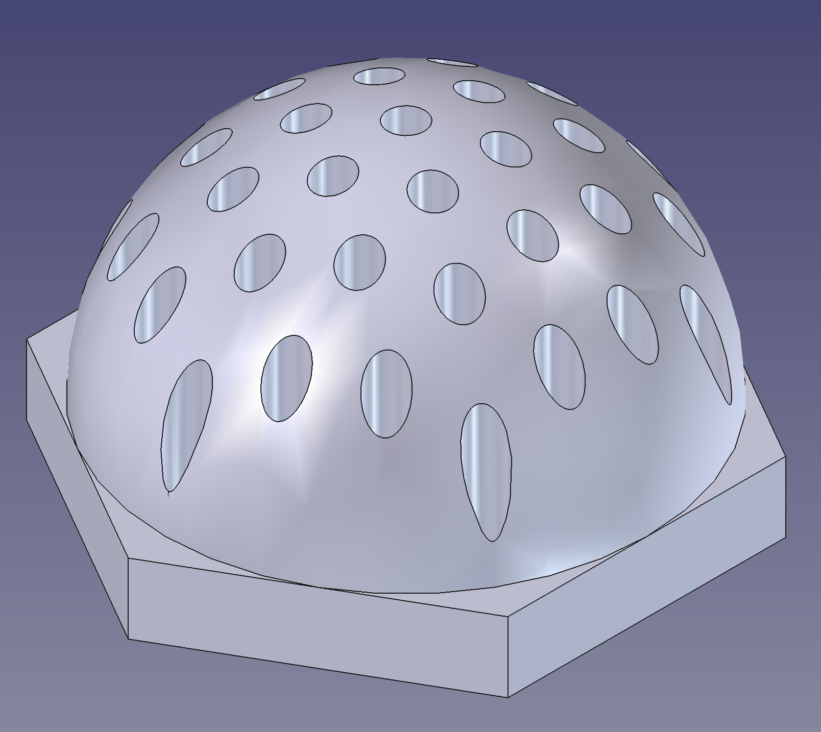
My idea was to channel the flat lights upwards to display on a hemisphere, as demonstrated in this convex diffuser base:
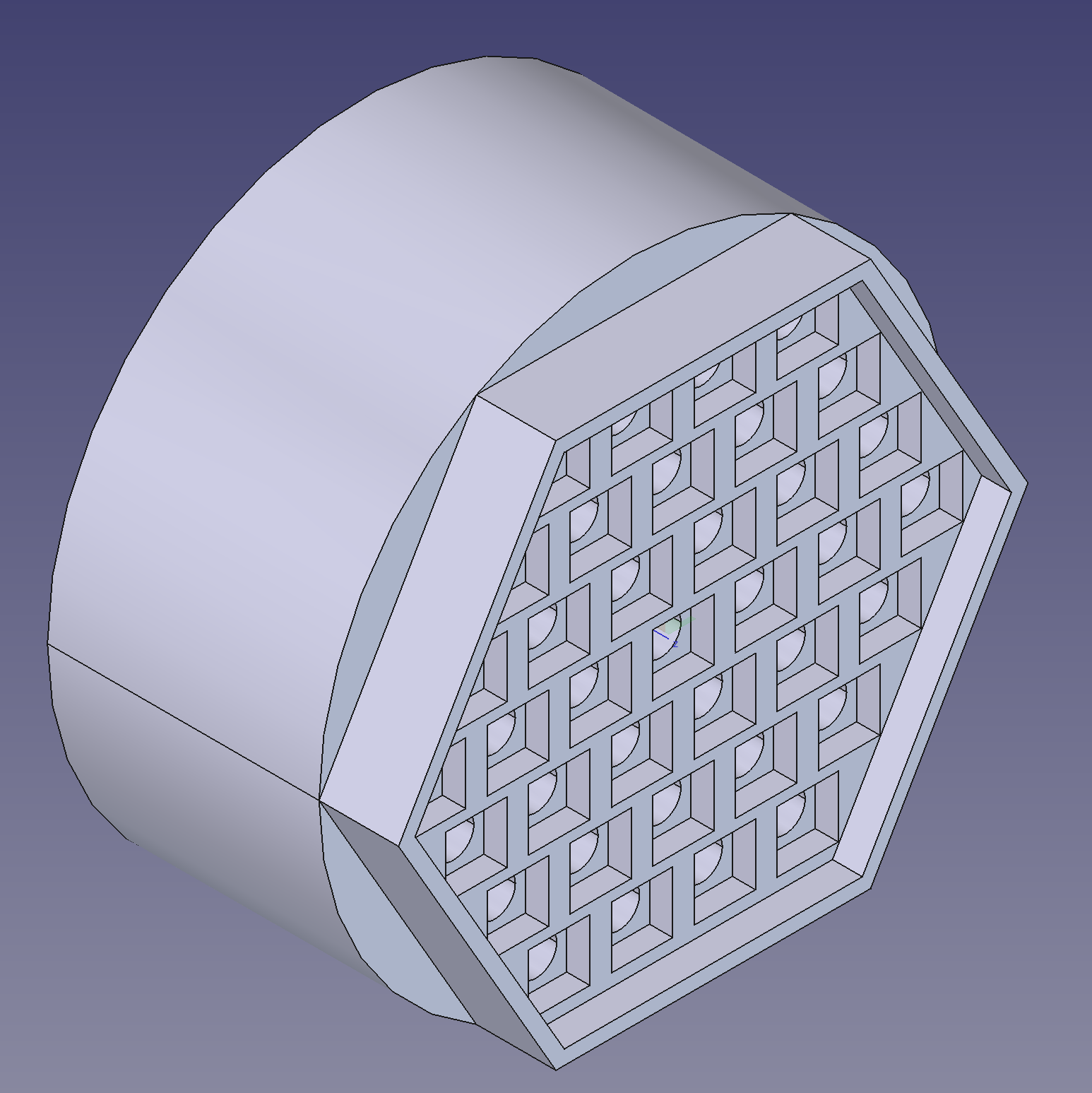
I initially printed this using white filament, which worked, but allowed too much light to bleed between pixels. This was an interesting effect and is a promising approach for filling even larger spaces, but wasn’t good for “cleaner” effects like the animated eye demo.
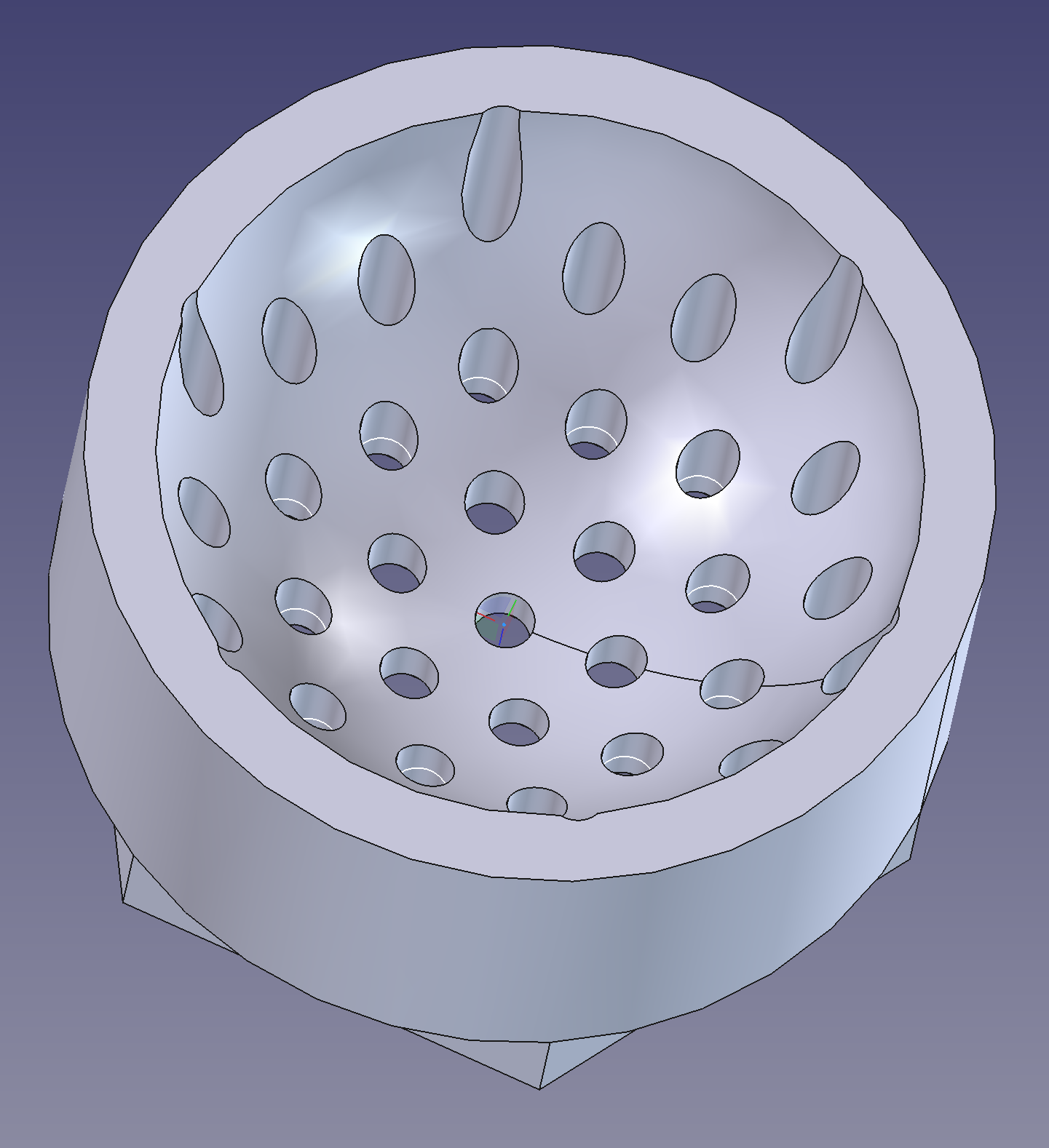
So, I printed another diffuser in slightly reflective black filament, this time as a concave form:
As I hope you can see in the demo, the effect was very clean. It was best viewed straight on, though, which can be hard on the eyes, as you’re staring directly at quite powerful lights. So, I designed a cap for each unit, with a brim, as shown in this cross-section:
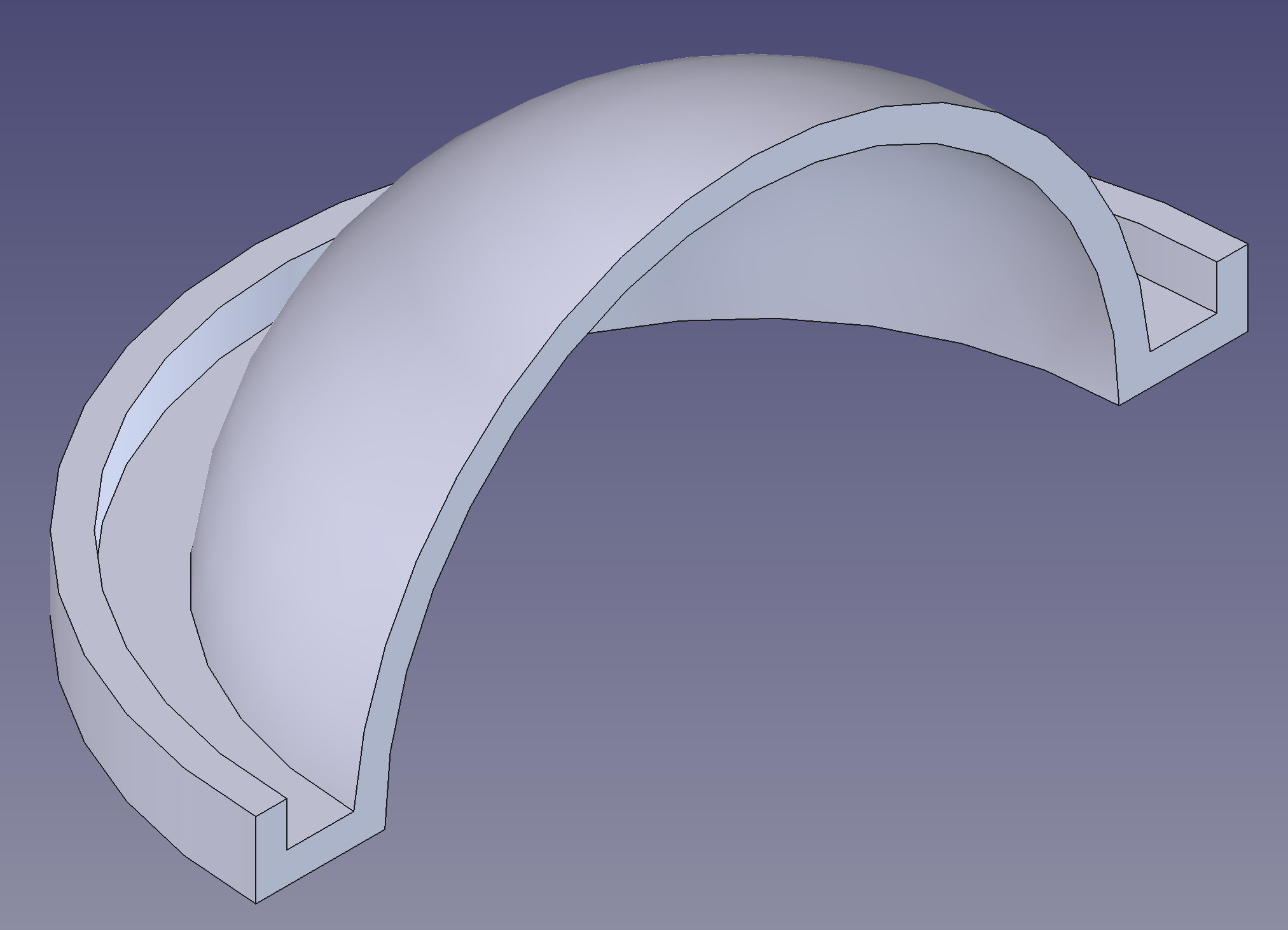
These were printed in white filament, as thin as I could manage without stringing out near the top of the hemisphere. They turned out very well, they spread out the light once it reaches the desired location and even out the brightness so you can comfortably look directly at the unit from above, and also see it from the sides.
After seeing both the concave and convex versions up close with working lights, I think I’ll use the convex version for most projects, as it definitely reads as more three dimensional. I like the concave variant, though, for cases in which you want the outside of the project to be flat or where you want to create a space for someone to stare into, for example, covered by an eyepiece.
On a side note, while I was making the caps, I accidentally made something like a Fresnel lens, but hemispherical, and with just the distortion (rings) and no magnification. Caps printed with the base resting on the print plate end up with a pattern of concentric layer lines as the hemisphere is built up.
Caps printed on edge ended up with layer lines produced a different effect, less of a starburst, and more like lights reflected on a wet road. I’ll definitely use these techniques in future diffusers.
The Demo
After a lot of trial and error, I managed to record a demo of the work in progress on my YouTube channel:
I’m pretty happy with what I learned, and the effect is pretty good, especially in person.
Follow-Up Work
The biggest issue at the moment is that power cycling or resetting the microcontroller results in a “blue pixel of death” rather than fully restarting:
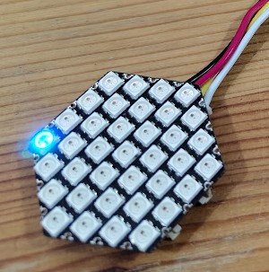
I need to narrow down whether this is a feature of software stack I’m using, the microcontroller(s) I’m using, or the Hex Unit itself.
On the software side, I still use the Pico SDK with this wrapper around the Adafruit Neopixel library. The wrapper is not updated often, and I suspect is the limiting factor in the maximum frame rate I can achieve in my animations.
I had long planned to try out FastLED. FastLED can apparently work as a standalone library, but their demos are made for Arduino and PlatformIO, so I figured I’d start by running their demos on a compatible unit just to see.
Speaking of compatible units, I did try narrowing down whether this was specific to a particular microcontroller. I tried various RP2040 and RP2035 units from various manufacturers, all of them have the same problem. The next stage is to try something totally different, and something designed to work with the Hex Unit. I got this cute little m5stack ESP unit to try with Arduino/FastLED.
I also ordered one of the m5stack NeoHEX units. It’s a drop-in replacement for the original, and I can quickly confirm if it has the same issue. I’m also curious whether the updated unit is any different in terms of brightness, power requirements, or ease of use.
In addition to making this stable enough to run after a restart or reset, I also need to figure out how to power it with a battery and how to charge the battery. I’m thinking of getting a newer microcontroller with built-in battery management, such as the Pimoroni Pico Lipo 2 XL W. I’ve also really enjoyed working with the Seed Studio Xiao rp2040 in other projects that I’ll write about soon. They make an inexpensive Seed Studio Grove Base that provides both the Grove connectors I need and battery charging, and you can break off the connectors you don’t need, so it’ll easily fit in a flashlight or box.
Once I solve the technical issues, I’ll start designing an enclosure to mount a Hex Unit in a box or flashlight, and write code to tailor the animations to the enclosure.
Conclusion
If you’ve made it this far, thanks for your time. It was a lot of work to describe, and I hope you enjoyed hearing about it. That’s it for now, you can see the code and diffuser models in a repository on GitHub.
Stay tuned for what’s next.