As covered in my last few posts, I’ve already designed a case for my “double rainbow” project, and then assembled it. Now I need to put the components in.
I almost waited to add this bit to the last post, and I’m glad I didn’t, as there were plenty of learning opportunities to work through. I needed to fit the following into my new case:
- The rp2040 round stamp carrier
- The larger neopixel “outer” ring
- A boost converter
- An IR receiver
- An external USB connector
- A LiPo battery
Although I did some informal fit testing with the Round Stamp Carrier and battery earlier, I hadn’t fit tested all the components. I went through one by one, taping or otherwise securing the components in the places I thought they should go, and confirming that the glass dome could still be secured. I found a couple of problems.
Problem the First, Not Enough Room Somewhere
The first deal breaker was that the exterior neopixel ring sat too high, and prevented me from securing the glass dome in place. I updated my design to make a channel for the ring, and then used a printout of that layer of the updated design to make a template to glue over the material I needed to remove.
After eyeing my chisels, files, and saws, I ended up buying a Dremel attachment for simple routing. This provides a “cup” to keep you moving along a plane, and a depth gauge to determine how far below that plane you want to cut. This assumes that you have two areas at the same level on either side of the cutting area, which I didn’t. I ended up resting one side of the cup on the top-most ring and calibrating the depth based on the number of layers. I worked around the ring and cut the channel:
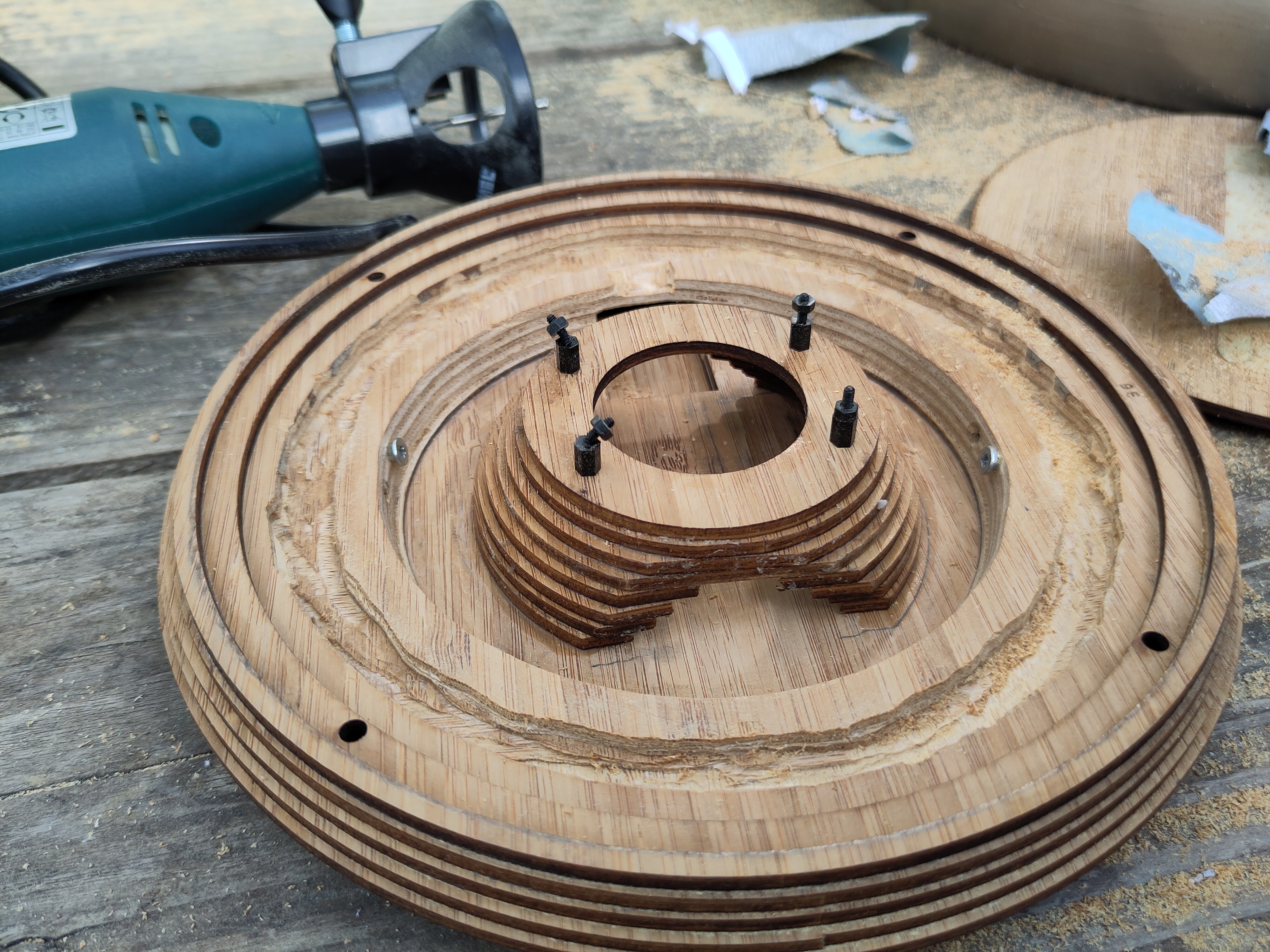
For what I needed to continue this project, the new channel was rough, but did the job, as the dome now fit again. If I wanted to do it any better, I would have had to do it before I glued everything together, and would have had to make a “jig” for the cup to butt up against. Good to know.
Problem the Second, Not Enough Room Somewhere Else
The second problem was with the USB extender I had intended to install, which turned out to be a comically tight fit, and left no room for the “neck” of the glass dome.
For now, I can take off the glass to access the built-in USB, I’ll add a proper external USB connection later.
Back to the Plan
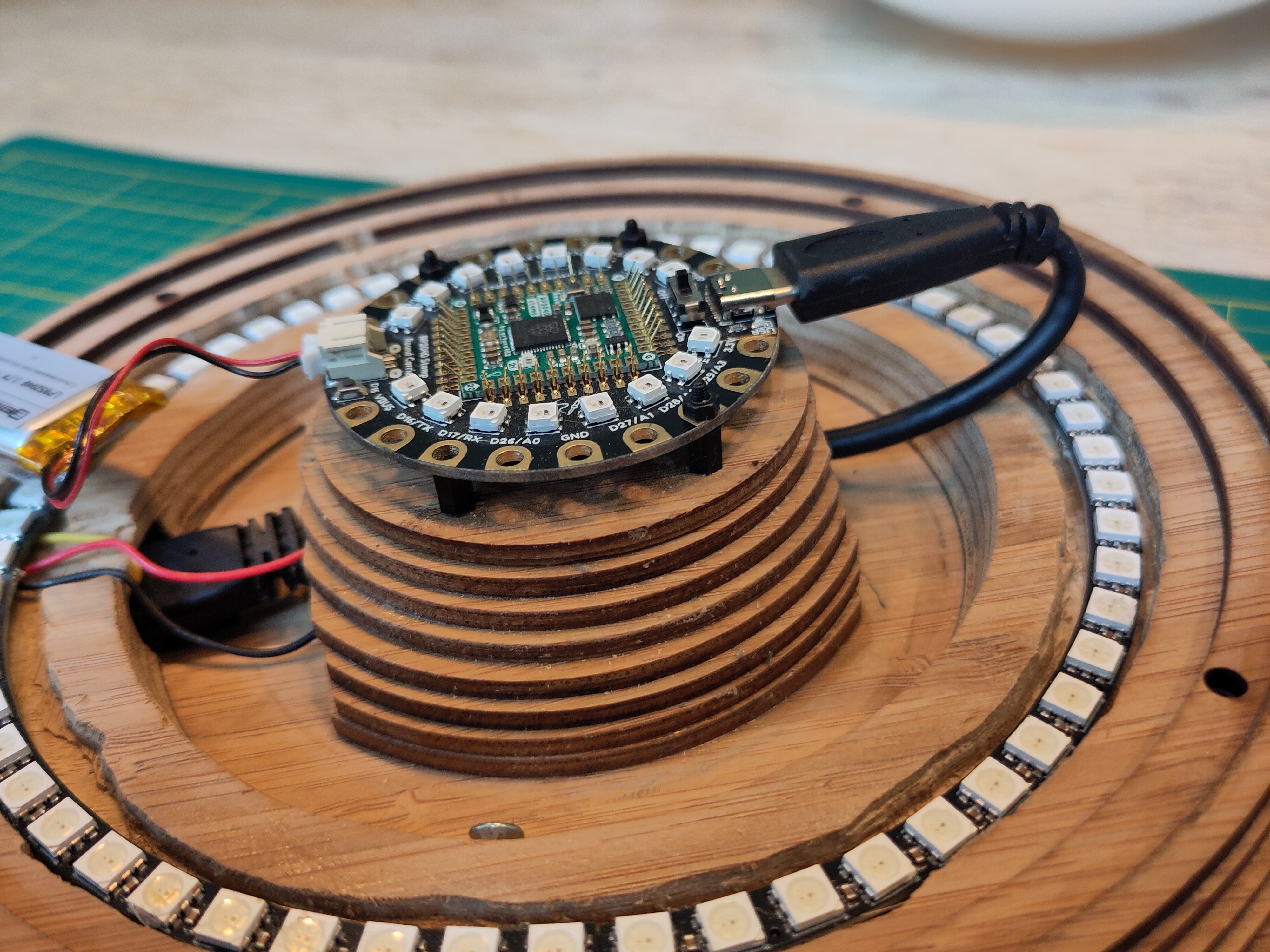
So now we’re done with the things I wasn’t expecting to have to do, and back to the things I planned on, namely wiring everything together. Here’s the overall circuit I want to make:

As a friend always points out, I could have collapsed most of this down into a single PCB. The external ring sits at a different level than the main unit, so I’d just need to wire that up, perhaps with a ribbon or grove connector. For now, I wanted to use up components I had on hand. Here it is during the “alligator clip” test:
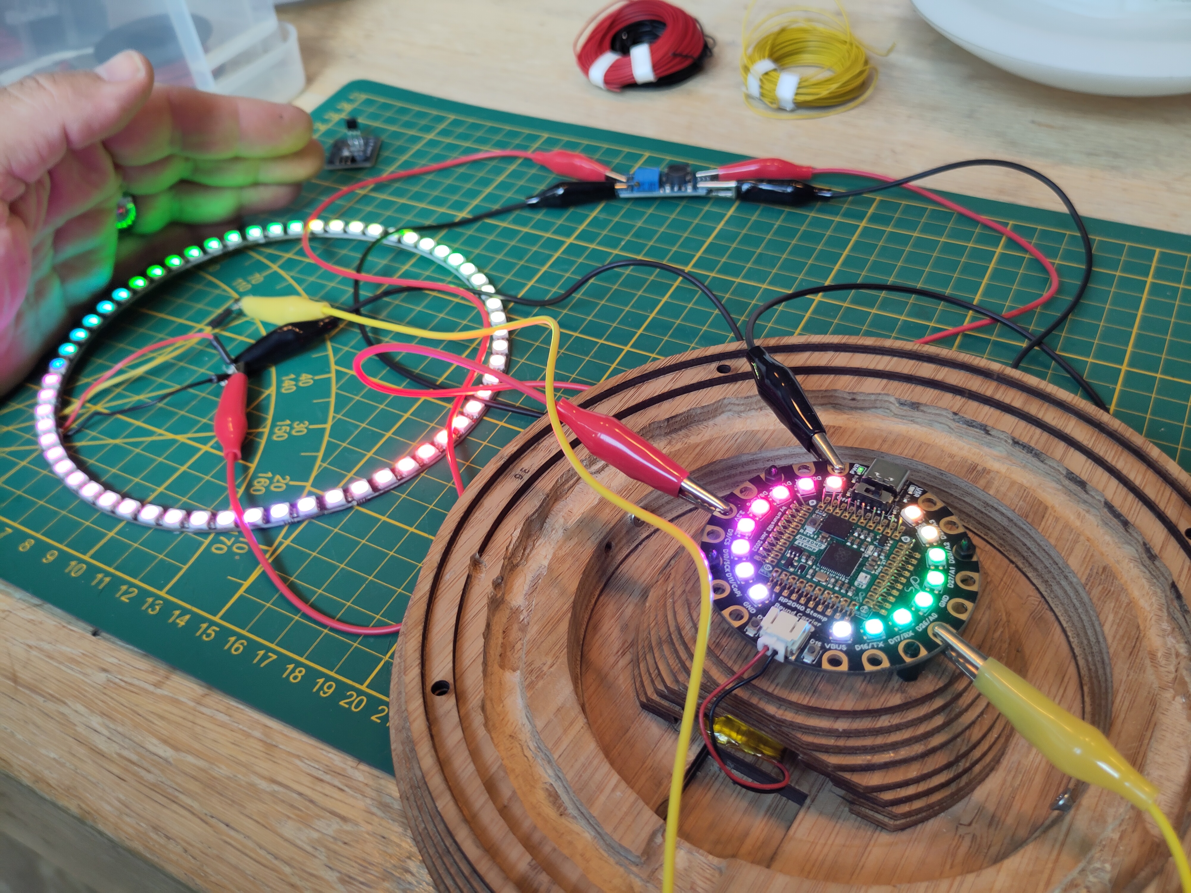
Boost Converter
In early prototyping, I noticed that the larger ring was often dim or discoloured, this is apparently expected behaviour if the voltage is too low. The round carrier also lets you connect to the 5 Volt feed provided by a USB connector, but I wanted something that would also work when using a LiPo battery.
The bit with the blue cube on it in the above photo is a boost converter which should ensure the outer ring would always get 5 Volts. This was my first time using one, this simple explanation was a big help in connecting and adjusting the boost converter (as they suggested, it took a lot more turns than I was expecting to adjust it to the right voltage).
Once the voltage conversion was adjusted, I wired the power for the ring to the boost converter, and the data pin to a GPIO pin on the round carrier. Although the colours are now much more consistent even when running on battery, there are glitches that appear if you use more than about 10% of maximum brightness, so I lowered the default brightness until I can figure out a better solution.
IR Receiver
Lots of our inexpensive “party” lights come with the same IR remote as this kit. Rather than make my own interface with buttons and a screen, I decided to learn how to use an IR receiver and figure out the codes used by that remote.
This went well enough in testing, but when mounting it for real, I initially tried to desolder the headers to make it easier to work with, and I suspect I may have cooked the little component. I’ll order a replacement without the headers and replace that later.
The Final Reveal
Once everything was put together, I recorded a short demo, which you can see on my YouTube channel:
I then installed the light on the wall, which was very easy since I could just print out the mounting bracket and use that as a guide in drilling the mounting holes:

I’ll definitely use that strategy again, it’s very easy and secure. Anyway, here it is in situ:
So, there you have it. There are a few key things to keep working on, notably the power and the IR receiver. At least I can put it on the wall for us to enjoy while I figure out the last wrinkles. First, I may treat myself and do something different for a while.
Stay tuned to see what’s next.