I recently resumed work on a NeoPixel light project I started last year, the “double rainbow”.
Last year I did a lot of experimenting with NeoPixel lights. These are individually addressable LEDs that can display a range of colours. I started working with them using the Solder Party RP2040 Round Carrier, which includes a ring of 16 NeoPixels. Early on, I was looking for option to diffuse the light to fill a volume, you can see some examples here:
One of the things I was experimenting with was a frosted glass dome that’s part of a light fixture I found at a thrift store. I eventually got the idea to make it into my own wall-mounted light powered by a RP2040 and NeoPixels.
As I sketched, I started playing with this cheaper version of a NeoPixel ring Adafruit makes, which has 60 NeoPixels. I had the idea to use the lights to represent seconds, but settled on making a “double rainbow” instead, as atmospheric lighting is the real goal.
I also wanted to make it fit in better with what we have, which are a bunch of inexpensive “party” lights that can be controlled using an IR remote. I spent some time learning to work with an infrared receiver and documenting the codes our existing lights use, and then made my code respond to the same codes appropriately. Most of the modes are fairly boring, solid colours, varying brightness, but I did my own thing for the “rainbow” modes the IR remote can trigger.
So Why Isn’t It Already Done?
I wrote most of the code last October, and even wired things up inside the light fixture using cardboard and hot glue to hold components in place. The project sat on the shelf after that because I couldn’t think of a good way to mount it.
The sides of the metal base nestle snugly against the glass dome, so there’s no option to run a cable out the side. I could run a cable out the back of the current base (the white bit in the video), but that keeps you from using the rear mounting holes. I could make a backing plate of some kind, but it wouldn’t match the metal and would increase the depth more than I’d like.
New Year, New Ideas
Cut to this month, when I realised I could just replace the whole base with something made from laser-cut wood or bamboo. I like organic materials for a lot of reasons, especially bamboo, which is fast-growing, inexpensive, safe to work with, and biodegrades when you’re done with it. It also smells nice when it’s cut or engraved with a laser.
The rest of this post will take you through the process of designing what will hopefully be my least crummy case so far.
What’s Measured Improves
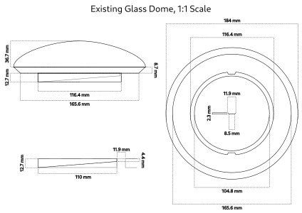
Before I can design a replacement for the existing base, I need to understand exactly how it fits around the glass dome. So, I broke out my calipers and started measuring things and making schematics I can refer to later in the process.
After a few minutes sipping coffee and tweaking paths, I ended up with schematics for the dome, and the base:
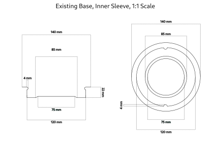
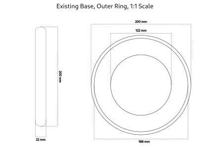
A key bit I need to keep from the white metal “sleeve” is the inner ring that snugly contains the base of the dome. I especially need the two bumps that secure the grooves on the bottom ring under the dome. Beyond that, I have the freedom to reimagine the overall shape to suit my goals.
Modelling the New Base
My goals for the new base, from practical to aesthetic:
- There has to be room for all components, wires and cables, including a panel-mount female USB-C connector.
- The existing glass dome has to fit snugly.
- The base should compliment the curve of the dome.
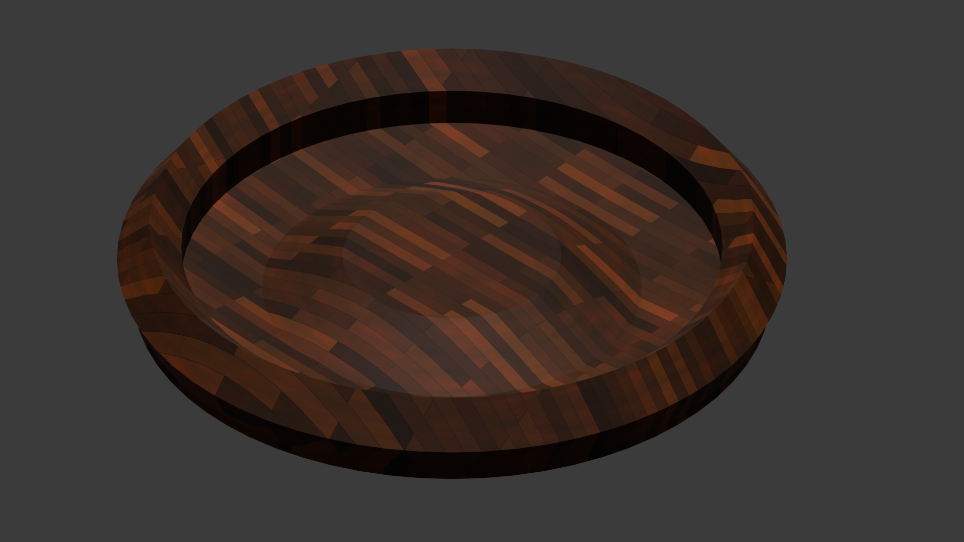
I started out mocking up designs in Blender, which went well enough:
Adding a Little (Necessary) Complexity
However, once I started thinking about the channels and panels for the USB connector, I realised I needed to make a multi-axis design. By that I mean that if I only work top-down, in rings, I’ll have a hell of a time affixing the panel mount female USB connector that will charge the battery. It’s far better to just cut a simple panel from the top down and insert it perpendicular to the rest of the design.
After a few happy hours in Inkscape, I made a top-down design, in rings, with a “pocket” for the USB panel to slide in to. Here’s the “fit test” I put together in Blender by importing, extruding, and then positioning all of the paths from my design:
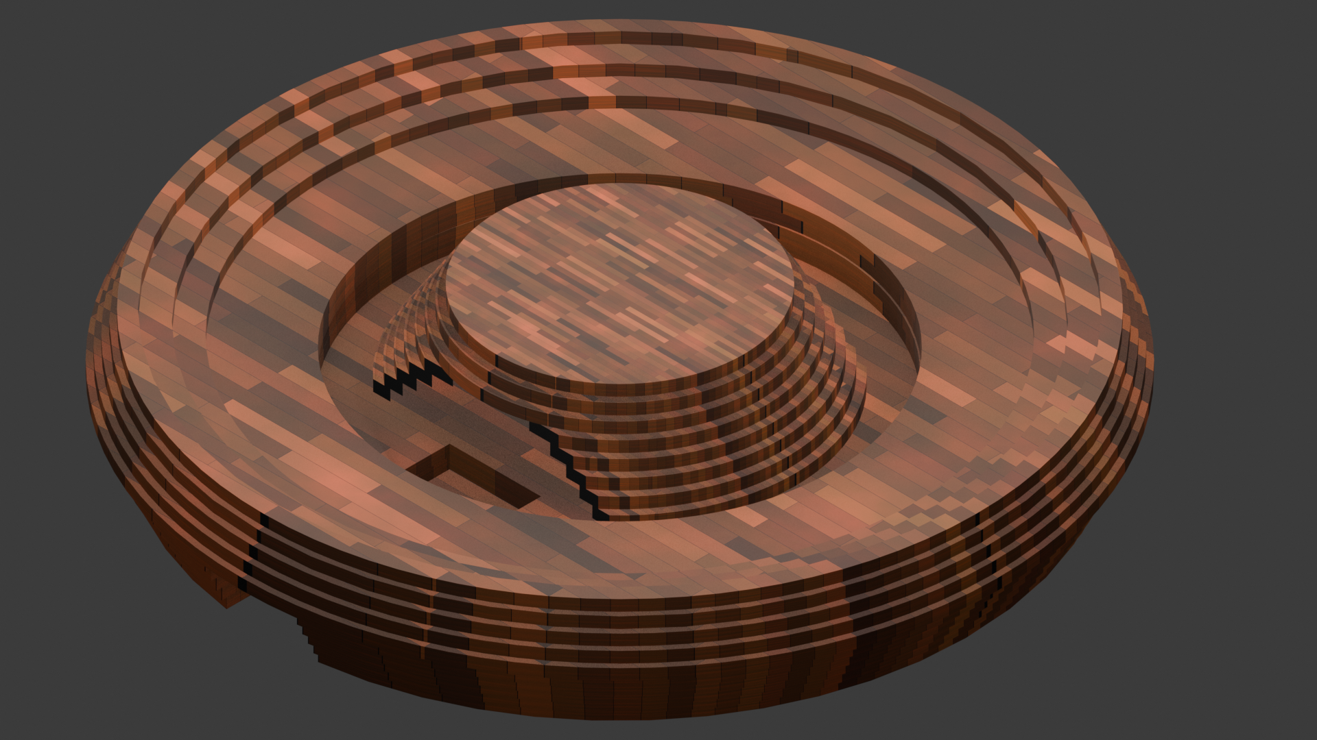
The keen-eyed among you may notice there are no “bumps” to hold in the glass dome. I plan to use an M3 wood screw on each side for this purpose, as they’re roughly the right size and stronger than anything I could do with laser-cut wood or bamboo.
Making It Easier to Assemble
This is by far the most complex laser cut project I’ve attempted, so I had to give some thought to how I’d make it easier to assemble everything and glue it together. I settled on three key approaches.
The first was simply to add labels to each level so I’d know what goes on top of what. Second, for the base plate and outer ring, I added holes that align through all the layers. I’ll use an M4 bolt, nut, and two washers in each of these to align all the layers and also provide light pressure while they’re being glued together.

This should work just fine for the base plates and most of the exterior rings.
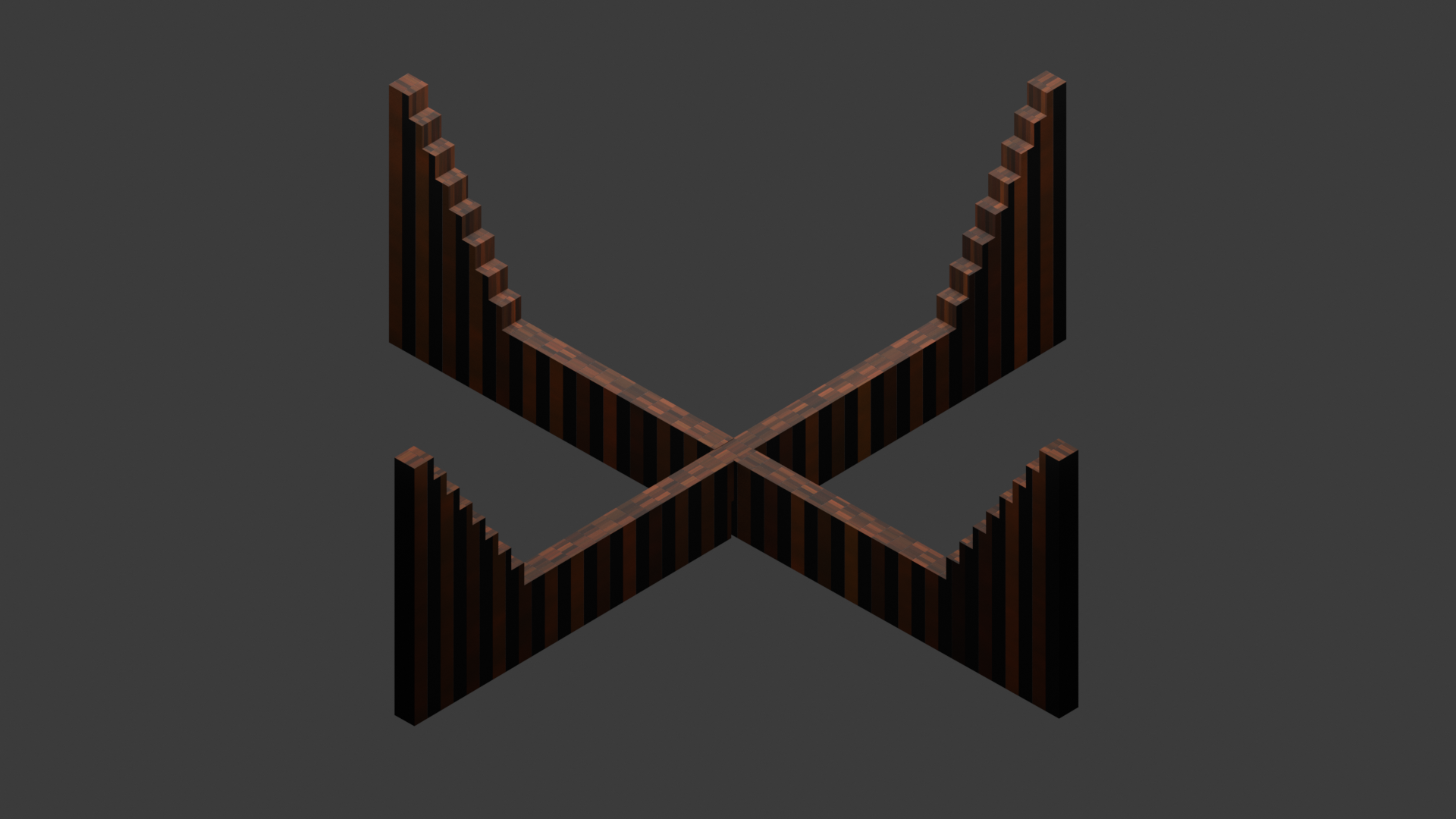
The interior “ziggurat” was a bit more of a challenge, as there isn’t enough overlap between the layers to make holes for clamping. For that I looked at the negative space outside the ziggurat, and made a simple “zig jig” I can lay the layers into from top to bottom. I tested the idea out in Blender, and it seems promising:
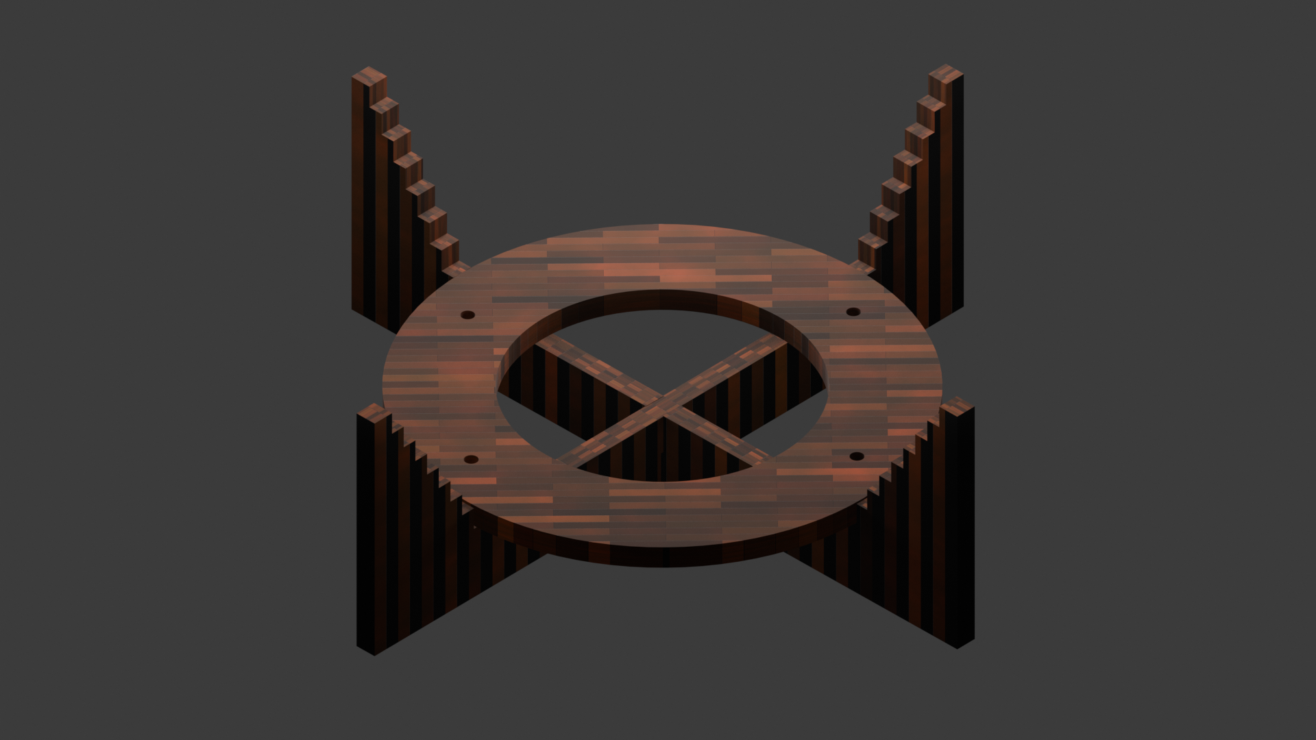
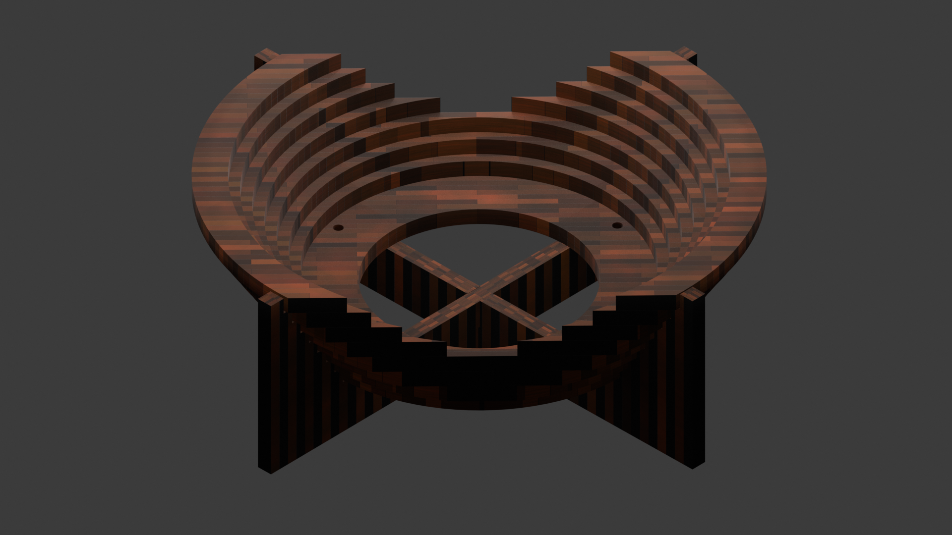
I thought of making a second jig for the interior, which might help with positioning and applying pressure, but might also be tough to wrangle. I decided to give it a go with just the outer jig and see how it goes.
“Late Stage Tetris”
With the design more or less settled, it’s time for what I call “late stage Tetris”. The goal is to end up paying for as little scrap material as possible. I rearranged things a few times, and ran what I had through the order creation tool provided by Snijlab, the laser cutting vendor I use. Here’s a thumbnail of the final design I sent them:
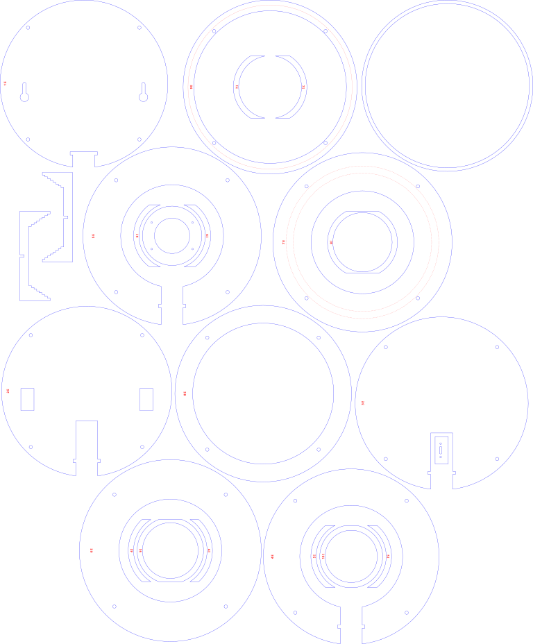
The blue lines will be cut through the material, and the red lines will be engraved (most are positioning guides and labels).
That’s a very small version, the actual design is 600 x 725 mm. Since I’m using a service with large-format commercial laser cutters, I can design everything on one sheet (They support up to 1200 x 600 mm). If I was working on a home printer, I would have had to use a bunch more material, probably a dozen or more A4 sheets of wood.
That’s It for Now
Anyway, this part of the project is out of my hands for now. The laser-cut pieces should be here by the end of the week, stay tuned for upcoming posts where I assemble the case, wire up the electronics, and mount it on the wall.