After working on my first watch face and making a second watch face for the hackathon, I had an idea for a new watch face, one that would require me to be able to rotate paths over time.
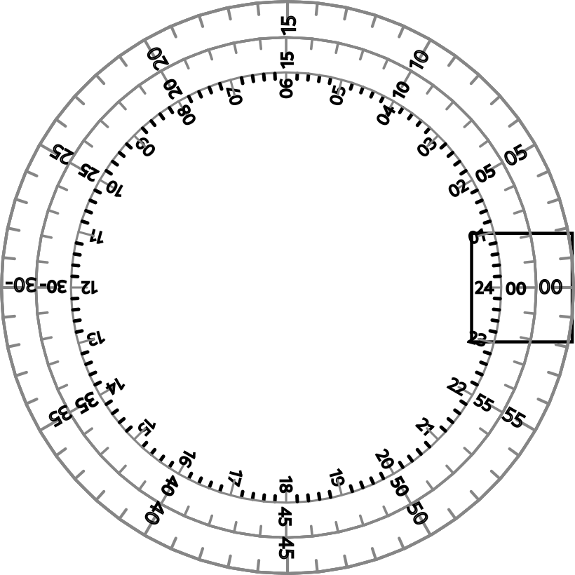
After I published my last watch face, I spent some time sketching new ideas in Inkscape. I started thinking about making the watch a window into a much larger moving space. This seems practical when working with vector images, as they can cover a huge space without taking much memory. Here’s a sketch of what I have in mind:

The black square on the right represents the watch face. There are three dials, one for hour, minutes, and seconds. The watch face is positioned so that the deals line up to display the current time. Each dial rotates through the watch face, moving proportionately to the time elapsed. The hour dial rotates once a day. The minute dial rotates once an hour, and the seconds dial rotates once a minute.
The rough effect is like reading a power meter in real time. Seconds fly by, minutes creep, hours crawl.
My Rough Approach
To make this work, I need a way to rotate an arbitary set of paths around a point of my choosing (in this case, far off screen to the left).
The C Pebble SDK provides a
gpath_rotate_to
function, which can rotate a path to an arbitrary angle. I had already read
through examples like this
one
covering how to hard-code paths, so I could have just made a path in code.
The thing is, I don’t want to create and manage a bunch of path data in code. Inkscape is a very comfortable place for me to sketch, I want to start with SVG images I create there, convert them for the Pebble, load them as a resource, and manipulate them in code.
PDC images can be loaded as GDrawCommandImage objects using the
gdraw_command_image_create_with_resource
function. As we saw in my latest work with
vectors, a
GDrawCommandImage contains a list of GDrawCommand objects. I can run a
callback on each of these and do something with it.
Looking at the underlying source for
GDrawCommand,
I can see that it has point data I can presumably use to create my own GPath
object. Some of the examples even cover drawing a single
command,
which was instructive.
So, what do we have to do to go from that point data to a rotateable path?
Today’s Heart of Darkness
In trying to patch together a GPath from a GDrawCommand, I ran into
compilation errors complaining about “dereferencing pointer to incomplete type”.
This is one of those errors that doesn’t give you a lot of clues where to turn.
Here’s a snippet to give you an idea what was failing:
static bool rotate_and_draw_command(GDrawCommand *command, uint32_t index, void *context) {
      // ...
      GPathInfo path_info = {
        .num_points = command->num_points,
        .points = command->points,
      };
Thankfully there were enough threads online like this
one
that clued me in. It turns out that the public-facing contract for
GDrawCommand does not actually allow access to its internal num_points and
points variables. Instead, you need to use getters and setters, as in:
static bool rotate_and_draw_command(GDrawCommand *command, uint32_t index, void *context) {
    // ...

    int num_points = gdraw_command_get_num_points(command);

    if (num_points > 0) {
      GPoint points[num_points];

      APP_LOG(APP_LOG_LEVEL_INFO, "Working with path: [\n");
      for (int index = 0; index < num_points; index++) {
        GPoint raw_point = gdraw_command_get_point(command, index);
        points[index] = GPoint(raw_point.x, raw_point.y);
        APP_LOG(APP_LOG_LEVEL_INFO, "  (%d, %d)\n", points[index].x, points[index].y);
      }

      APP_LOG(APP_LOG_LEVEL_INFO, "]\n");

      GPathInfo path_info = {
        .num_points = num_points,
        .points = points,
      };
With that fixed, I had an approach that compiled, but nothing was displayed.
Take Something like a Star to Test Your Code on, and be Tested
(With apologies to Robert Frost.)
So, I initially tested my work with a complex multi-layered set of paths that had both stroke and fill colours. I decided to create a simple image to help me understand where things were going wrong (and that would also clearly display rotation):

This also did not display. I quickly grabbed a hard-coded path from this example. This displayed, and also rotated (I’d optimistically already put that code in).
On a hunch, I started logging the location of the points for my star path.
[17:24:58] -dial-o-meter.c:129> Drawing image that is 148 wide and 148 tall...
[17:24:58] -dial-o-meter.c:58> Working with path: [
[17:24:58] -dial-o-meter.c:61>   (220, 518)
[17:24:58] -dial-o-meter.c:61>   (508, 512)
[17:24:58] -dial-o-meter.c:61>   (574, 231)
[17:24:58] -dial-o-meter.c:61>   (669, 504)
[17:24:58] -dial-o-meter.c:61>   (956, 480)
[17:24:58] -dial-o-meter.c:61>   (726, 654)
[17:24:58] -dial-o-meter.c:61>   (838, 920)
[17:24:58] -dial-o-meter.c:61>   (601, 755)
[17:24:58] -dial-o-meter.c:61>   (383, 944)
[17:24:58] -dial-o-meter.c:61>   (466, 668)
[17:24:58] -dial-o-meter.c:64> ]
Turns out the star somehow ended up far too large, like 800 pixels wide, when
it was meant to be 148x148.
I looked to see if the bounds were correct, i.e. if the path was being scaled to
fit the bounds. The bounds were 148x148, as expected.
To simplify the problem a bit, I edited a copy of the image to remove the data that Inkscape inserts, which leaves us with something that’s small enough to just show you:
<?xml version="1.0" encoding="UTF-8" standalone="no"?>

<svg
width="148"
height="148"
viewBox="0 0 148 148"
version="1.1"
xmlns="http://www.w3.org/2000/svg"
xmlns:svg="http://www.w3.org/2000/svg">

<g
transform="translate(-100.48515,-192.02759)">
<path
id="path1"
style="fill:none;stroke:#000000;stroke-width:2;stroke-linecap:round"
d="m 129.22064,254.65742 36.04611,1.31054 10.21395,-34.59356 9.89246,34.68687 36.05672,-0.97595 -29.93223,20.12712 12.07031,33.9904 -28.39159,-22.24764 -28.59685,21.98317 12.38527,-33.8769 z"
/>
</g>
</svg>
After a quick refresher on the syntax for the path
element, I continued editing
the SVG to:
- Draw everything around
0,0(see below). - Ensure that all paths were lines (and not curves or arcs).
- Ensure that all points were on coordinates that could be expressed using only integer values.
I also used the space-delimited syntax and spelled out every draw command (in
this case l for “line”) for each point. Hopefully that’s not actually
necessary.
After all that, I ended up with:
<?xml version="1.0" encoding="UTF-8" standalone="no"?>
<svg
   width="148"
   height="148"
   viewBox="0 0 148 148"
   version="1.1"
   xmlns="http://www.w3.org/2000/svg"
   xmlns:svg="http://www.w3.org/2000/svg">
   <path
      style="fill:none;stroke:#000000;stroke-width:2;stroke-linecap:round"
      d="m0 -35 l10 35 l36 -1 l-30 20 l12 34 l-28 -22 l-29 22 l12 -34 l-29 -20 l36 1 z"
   />
</svg>
I must have done something right, because for the first time the
pdc_tool didn’t throw any warnings
when converting my SVG to a PDC file. When opening the PDC file on the Pebble
and pulling out the point data, the logging mechanism now reports:
[13:20:00] -dial-o-meter.c:129> Drawing image that is 148 wide and 148 tall...
[13:20:00] -dial-o-meter.c:58> Working with path: [
[13:20:00] -dial-o-meter.c:61>   (452, 68)
[13:20:00] -dial-o-meter.c:61>   (532, 348)
[13:20:00] -dial-o-meter.c:61>   (820, 340)
[13:20:00] -dial-o-meter.c:61>   (580, 500)
[13:20:00] -dial-o-meter.c:61>   (676, 772)
[13:20:00] -dial-o-meter.c:61>   (532, 596)
[13:20:00] -dial-o-meter.c:61>   (300, 772)
[13:20:00] -dial-o-meter.c:61>   (396, 500)
[13:20:00] -dial-o-meter.c:61>   (164, 340)
[13:20:00] -dial-o-meter.c:61>   (452, 348)
[13:20:00] -dial-o-meter.c:64> ]
It’s still too big, but with the simpler SVG, we have a lot clearer idea what
the values should be now. The first point should be 57,9. The second point
should be 10 pixels to the right, and 35 down. Instead, the second point is
80 pixels to the right and 280 pixels down. The numbers are always off by a
factor of 8.
This might still suggest some kind of scaling factor, but the fact that it’s off
by a power of two is suspicious, i.e. 2 shifted three bits to the left is
16. Although I’ll have to dive in further to figure out exactly what’s going
on, for now, I simply shifted the bits back in the other direction, as in:
      APP_LOG(APP_LOG_LEVEL_INFO, "Working with path: [\n");
      for (int index = 0; index < num_points; index++) {
        GPoint raw_point = gdraw_command_get_point(command, index);
        points[index] = GPoint(raw_point.x >> 3, raw_point.y >> 3);
        APP_LOG(APP_LOG_LEVEL_INFO, "  (%d, %d)\n", points[index].x, points[index].y);
      }

      APP_LOG(APP_LOG_LEVEL_INFO, "]\n");

      GPathInfo path_info = {
        .num_points = num_points,
        .points = points,
      };

      GPath *path = gpath_create(&path_info);
      gpath_move_to(path, GPoint(35,35));
      gpath_rotate_to(path, rotate_image_context->angle);
This produces the following log output:
[13:31:57] -dial-o-meter.c:58> Working with path: [
[13:31:57] -dial-o-meter.c:62>   (56, 8)
[13:31:57] -dial-o-meter.c:62>   (66, 43)
[13:31:57] -dial-o-meter.c:62>   (102, 42)
[13:31:57] -dial-o-meter.c:62>   (72, 62)
[13:31:57] -dial-o-meter.c:62>   (84, 96)
[13:31:57] -dial-o-meter.c:62>   (66, 74)
[13:31:57] -dial-o-meter.c:62>   (37, 96)
[13:31:57] -dial-o-meter.c:62>   (49, 62)
[13:31:57] -dial-o-meter.c:62>   (20, 42)
[13:31:57] -dial-o-meter.c:62>   (56, 43)
[13:31:57] -dial-o-meter.c:65> ]
The first point is at 57,9 (minus one each time), and the second point is
10 pixels left and 35 pixels right. The pixel values match the starting
point and the distances used in the path, so the size is now good.
The last bit I needed was to figure out how the rotation behaved. By default,
the path rotated around the top left corner of the image. Thankfully, the same
pathing example I used
earlier
used a technique I needed, which was to orient the paths around 0,0 as the
centre.
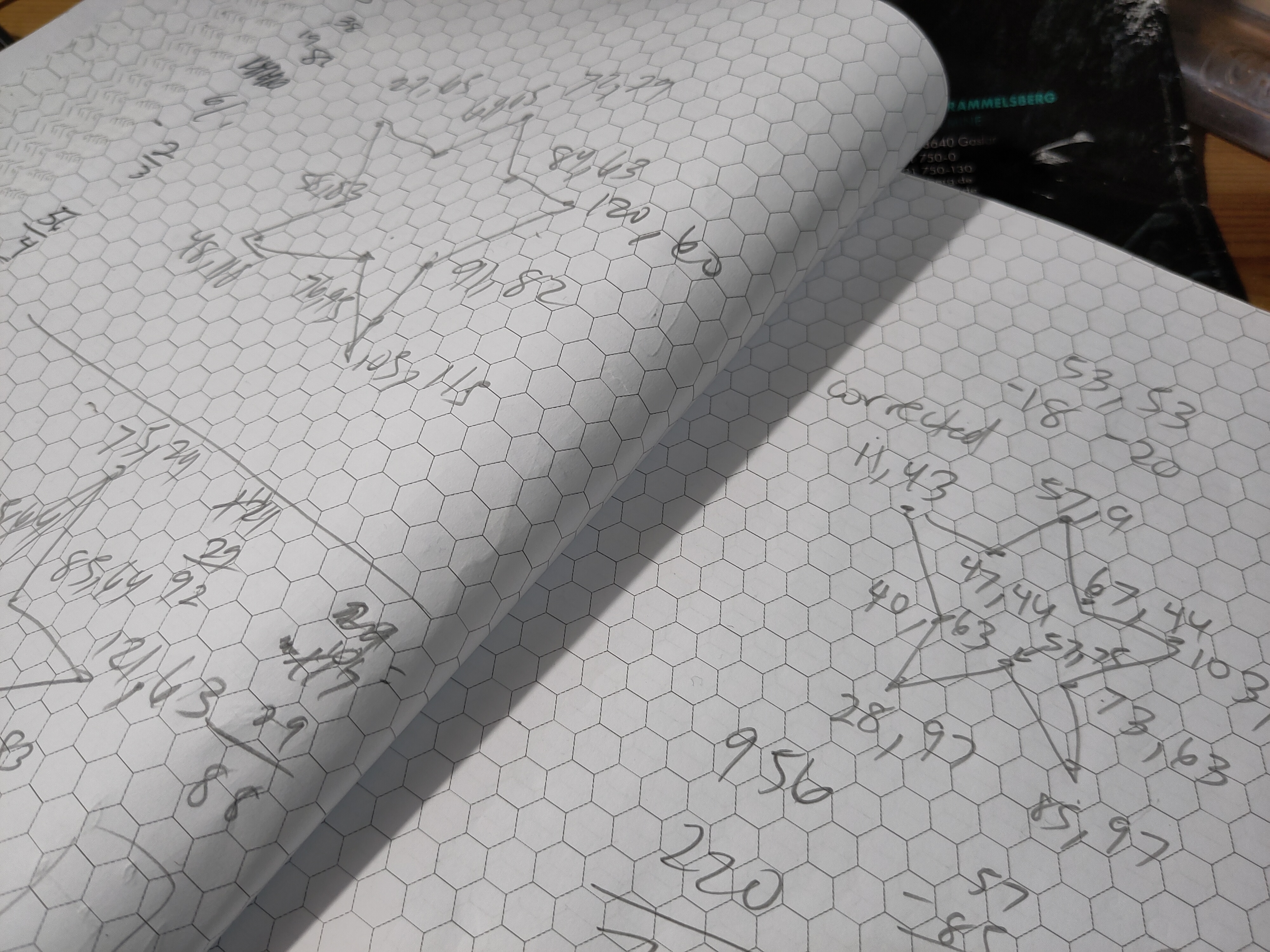
I made a few diagrams to figure out the final values:

Let’s look again at the SVG path data:
   <path
      style="fill:none;stroke:#000000;stroke-width:2;stroke-linecap:round"
      d="m0 -35 l10 35 l36 -1 l-30 20 l12 34 l-28 -22 l-29 22 l12 -34 l-29 -20 l36 1 z"
   />
Everything is drawn surrounding 0,0. Apparently you need to draw “clockwise”
in older versions of the Pebble SDK, so even though my target platform is newer,
I did that as well. Once I followed the same conventions as the example image, I
was able to move the path wherever I wanted and rotate it around its centre.
Conclusion
All that may not seem like a lot of progress, but I learned a lot, and I’m gratified that I have the foundation I need to keep working on the new project.
I still need to do a lot of work to prepare the complex SVG images for the real
watch. Although it was fun making diagrams for the ten points in my “star”, I
really hope the most I have to do is figure out the centre point of each path
and update the first “move” command in each path to move the centre point to
0,0.
Anyway, that’s it for now. I’ll make a new post including a link to the repo once I actually have things working. Stay tuned to see whatever’s next.